

 EN
EN
 English
 Français
 Español
 عربى
عربىA diaphragm pump diagram is a cross-section illustration that shows every internal part of the pump and how those parts work together to move fluid. A diaphragm pump is a positive-displacement pump that uses a flexible membrane, called the diaphragm, to alternately expand and contract a chamber, creating suction on the inlet and pressure on the outlet. The diagram reveals which parts contact the fluid, which parts wear first, and why an air-operated design differs from an electric one. Reading it correctly lets you assess any manufacturer's specifications with confidence.
Content
- 1 What Is a Diaphragm Pump?
- 2 Anatomy of a Diaphragm Pump: Key Parts in the Diagram
- 3 How to Read the Working Cycle in a Diaphragm Pump Diagram
- 4 Pneumatic vs. Electric Diaphragm Pump Diagrams
- 5 Choosing the Right Materials by Reading the Diagram
- 6 Common Applications
- 7 Frequently Asked Questions
- 8 Conclusion: Use the Diagram to Buy the Right Pump
What Is a Diaphragm Pump?
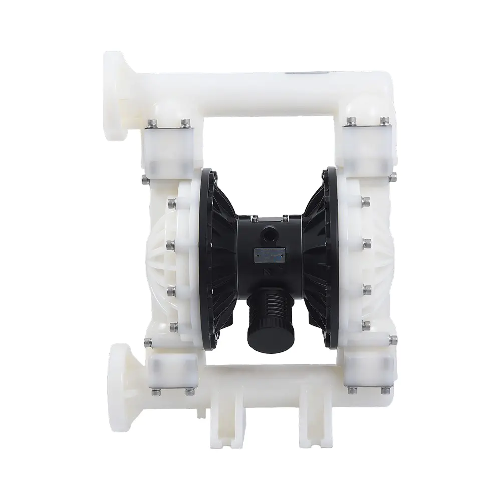
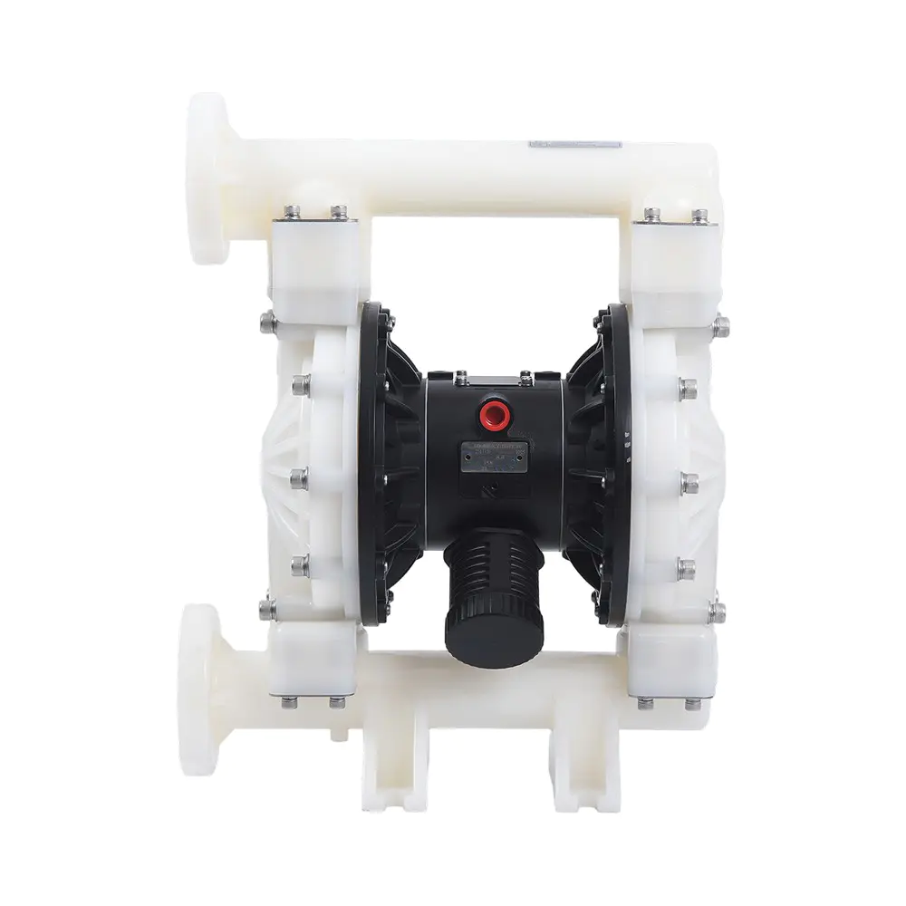
A diaphragm pump is a positive-displacement pump that moves fluid by flexing a flexible membrane back and forth inside a sealed chamber. The diaphragm separates the pumped liquid from the drive mechanism. When it pulls away from the chamber wall, volume increases and pressure drops, so fluid enters through the inlet check valve. When it pushes toward the wall, volume decreases and pressure rises, so fluid is forced out through the outlet check valve.
Because the diaphragm completely seals the fluid from the driving components, there is no rotating shaft seal to leak. This is why diaphragm pumps are the default choice for abrasive slurries, corrosive chemicals, viscous fluids, and applications where spills are unacceptable. Most are self-priming and can run dry for short periods, giving them a flexibility other pump types do not offer.
Anatomy of a Diaphragm Pump: Key Parts in the Diagram
The key parts in a diagram are the diaphragm, two fluid chambers, four check valves, the manifolds, and, on air-operated models, the air-distribution system. Knowing what each part does helps you compare designs and plan maintenance.
Fluid-Side Components
- Diaphragm: The flexing membrane that creates the volume change. Common materials are EPDM, PTFE, and NBR; the choice affects chemical compatibility and service life.
- Fluid chamber: The cavity whose volume changes as the diaphragm flexes; its material determines resistance to the pumped fluid.
- Valve balls and seats: Located at the inlet and outlet, they form the check valves. A worn ball or seat is the most common cause of lost capacity.
- Suction and discharge manifolds: The connections between the chamber and the piping; their port size limits the maximum flow rate.
Air-Side Components
- Air valve: The block that alternately feeds compressed air to each diaphragm. In an AODD diagram, this part controls the whole stroke cycle.
- Center block: The structural middle section that houses the air valve and connects the two outer fluid chambers.
- Connecting rod: Links the two diaphragms so they move in opposite directions; one side is in suction while the other is in discharge.
- Exhaust muffler: Silences the spent drive air and protects the air valve from contamination; in cold climates it can ice over if the air is not dried.
| Part | Side | Function |
|---|---|---|
| Diaphragm | Fluid / drive | Creates the volume change and separates the fluid from the drive mechanism |
| Fluid chamber | Fluid | Expands for suction, contracts for discharge |
| Valve ball and seat | Fluid | One-way check valve that prevents backflow |
| Manifold | Fluid | Inlet and outlet connection points for the piping |
| Air valve | Drive | Alternates compressed air between the two diaphragm chambers |
| Center block | Drive | Holds the air valve and joins the two pump halves |
| Connecting rod | Drive | Synchronizes the movement of the two diaphragms |
| Muffler | Drive | Reduces exhaust noise and filters the outgoing air |
How to Read the Working Cycle in a Diaphragm Pump Diagram
The operating cycle in any diagram is built from two opposing strokes: suction and discharge. Follow the flow path in the drawing, and you will see the valve balls move in a fixed sequence.
- Identify the drive mechanism: an air valve or a motor.
- Follow the fluid path: inlet manifold, chamber, valve ball, outlet manifold.
- Check the wetted material list below the drawing for chemical compatibility.
The Suction Stroke
During suction, the diaphragm moves away from the fluid chamber. The chamber volume increases, the internal pressure drops below the inlet line pressure, and the inlet valve ball lifts to admit fluid. The outlet line pressure pushes the outlet valve ball onto its seat, closing the discharge line.
The Discharge Stroke
During discharge, the diaphragm moves toward the chamber. The volume decreases, pressure rises, and the outlet valve ball lifts off its seat to push fluid into the discharge line. The inlet valve ball is forced onto its seat, preventing backflow.
Why the Double-Diaphragm Design Matters
In an AODD pump, the two diaphragms are connected by a common shaft, so one diaphragm is always in suction while the other is in discharge. This gives a nearly continuous flow compared with a single-diaphragm design. The air valve reverses the air supply mechanically, without sensors, which is why these pumps are reliable in hazardous or wet environments.
Pneumatic vs. Electric Diaphragm Pump Diagrams
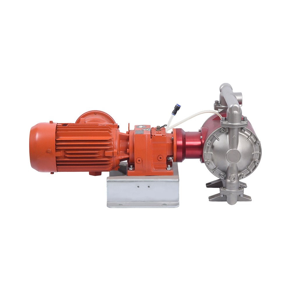
The most important thing a diagram tells you is how the diaphragm is driven, because that decides the pump's cost, flow control, and site suitability. A pneumatic diagram shows an air valve between the two diaphragms and no motor; speed is set by adjusting the air supply. An electric diagram shows an AC motor and eccentric pushing the diaphragm; it delivers steady, metered flow but needs electrical protection.
| Aspect | Pneumatic diaphragm pump | Electric diaphragm pump |
|---|---|---|
| Drive medium | Compressed air | AC motor |
| Flow control | Adjustable air regulator | Motor speed or stroke length |
| Dry-run capability | Generally safe for short periods | Often requires dry-run protection |
| Hazardous area rating | No electrical spark, intrinsically safe | Requires explosion-proof motor |
| Typical duty | Viscous, abrasive, solids-laden fluids | Chemical dosing, metering, clean fluids |
If you need to transfer abrasive slurries or flammable solvents, an air-operated diaphragm pump is the safer choice because the fluid never comes near an electrical component. For continuous dosing with a stable, repeatable flow, the electric diaphragm pump range is often a better fit. The diagram in each datasheet shows the exact layout, so you can verify valve positions, port sizes, and wetted materials before ordering.
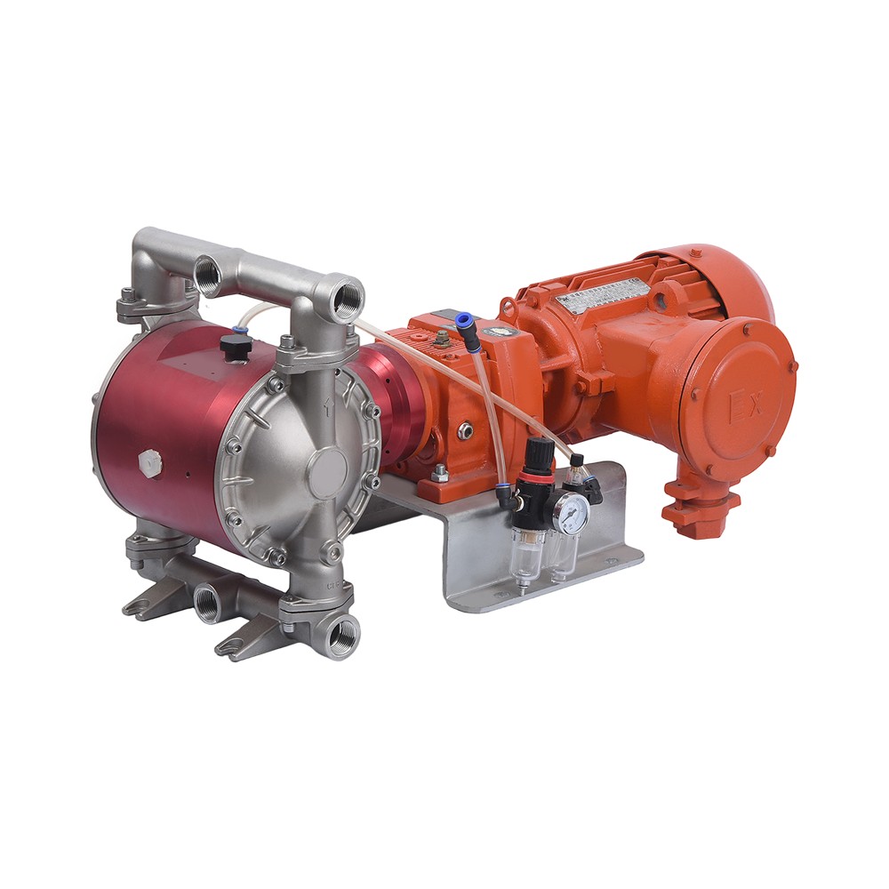 Custom Electric Diaphragm Pump High Flow for Water Transfer Manufacturers, FactoShanghai Haoyang Pump Valve Manufacturing Co., Ltd is top China Electric Diaphragm Pump High Flow for Water Transfer manufacturers and cu...View Product →
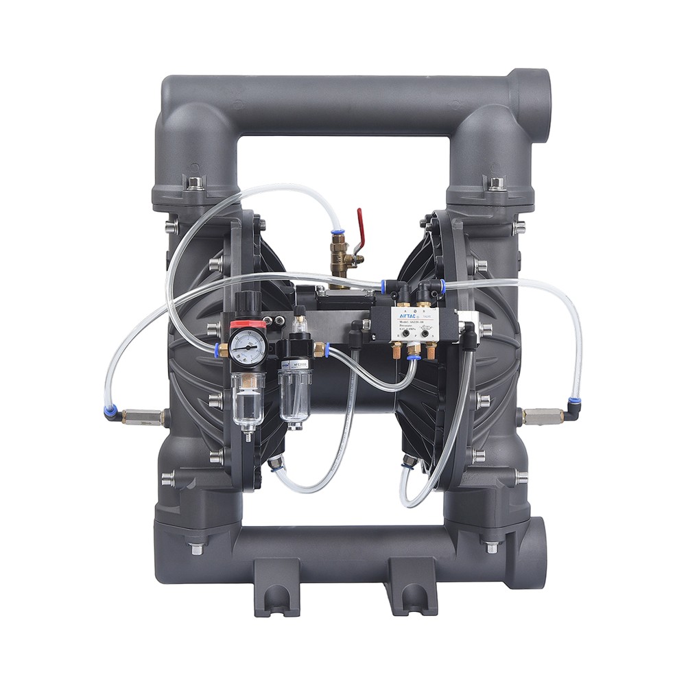
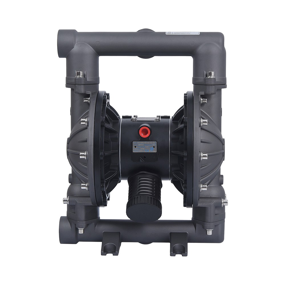 Pneumatic Diapagm Pump Manufacturer | AODD Diapagm PumpShanghai Haoyang Pump Valve Manufacturing Co., Ltd. is a China pneumatic double diapagm pump manufacturers and AODD diapagm pump factory,...View Product →
Choosing the Right Materials by Reading the Diagram
The parts that touch the pumped fluid, the chambers, manifolds, valve balls, and diaphragm, are the wetted parts, and their material determines chemical compatibility. The diagram's bill of materials lists them separately, which is exactly what you need when comparing pumps.
- Polypropylene (PP): Economical and resistant to most acids and alkalis at moderate temperatures; common in chemical transfer and plating lines.
- PVDF (Kynar): Handles strong solvents and higher temperatures; used in pharmaceutical and semiconductor-chemical applications.
- Aluminum: Light and inexpensive, but limited to non-corrosive fluids such as water, oils, and paints.
- Stainless steel: Resists aggressive chemicals, tolerates high temperatures, and meets hygiene requirements for food, beverage, and pharmaceutical lines.
In a food plant that uses caustic washdown solutions and hot water, a 1-inch stainless steel diaphragm pump is a natural choice because it combines chemical resistance with hygiene compliance. For corrosive chemicals at ambient temperature, the polypropylene and PVDF series offer a lower purchase cost with fully acceptable service life.
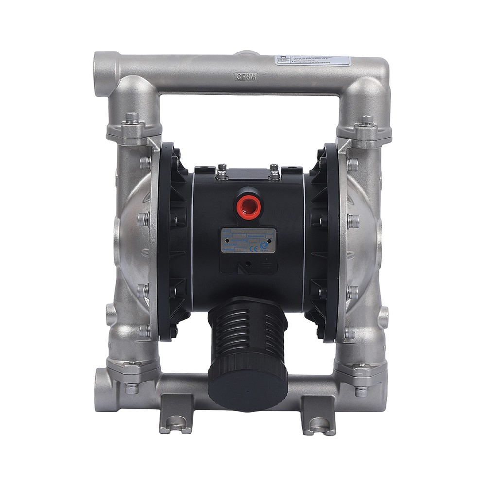 Custom 1Shanghai Haoyang Pump Valve Manufacturing Co., Ltd is top China 1' Stainless steel diaphragm pump manufacturers and custom factory,Fluid ...View Product →
Common Applications
Diaphragm pumps are used in nearly every process industry where leakage, contamination, or dry running is a concern. Typical duties include:
- Chemical dosing and water treatment
- Paint, ink, and coating transfer
- Ceramic slurry and clay pumping
- Mining and mineral processing
- Food and beverage transfer
- Pharmaceutical compounding
- Printing, paper, and textile production
- Construction dewatering and marine bilge pumping
This range explains why the diagram matters before installation: two pumps with identical external dimensions can have different wetted materials, valve seat sizes, or diaphragm stiffness. You will find additional field guidance in our industry application notes.
Frequently Asked Questions
These are the questions engineers and buyers ask most often when they examine a diagram.
What does a diaphragm pump diagram show?
It shows the internal arrangement: diaphragm, fluid chambers, valve balls and seats, manifolds, and the drive mechanism. Use it to understand the operating principle, check material compatibility, and order spare parts.
How many parts are there in a diaphragm pump?
A typical diaphragm pump contains between 15 and 25 parts, but the core components are few: the diaphragm, two fluid chambers, four valve balls with seats, and the drive system. The diagram lets you count them and understand what each one does.
What is the difference between the fluid side and the air side in an AODD diagram?
The fluid side is the outer section that contacts the pumped media. The air side is the center section with the air valve, connecting rod, and muffler; it never contacts the product.
Can I run a diaphragm pump dry?
Air-operated diaphragm pumps can generally run dry for short periods because the diaphragm does not need the fluid for lubrication. Electric models are more sensitive and should be protected with a low-level switch.
Why does a diaphragm pump need a pulsation dampener?
Each stroke delivers a discrete volume of fluid, so the discharge is naturally pulsed. A pulsation dampener absorbs the pulse and smooths the flow, protecting instruments and piping.
Conclusion: Use the Diagram to Buy the Right Pump
A diaphragm pump diagram is not just a technical drawing; it is a purchasing, maintenance, and troubleshooting tool. Start by identifying the wetted parts and their materials, then check the drive type and port sizes, and only then compare prices. If you need help selecting a configuration for an abrasive, corrosive, or hygienic duty, our team publishes detailed drawings and material lists for every model. You can start your review by visiting our company homepage, or contact our engineers directly with your fluid type, temperature, and flow rate.