

 EN
EN
 English
 Français
 Español
 عربى
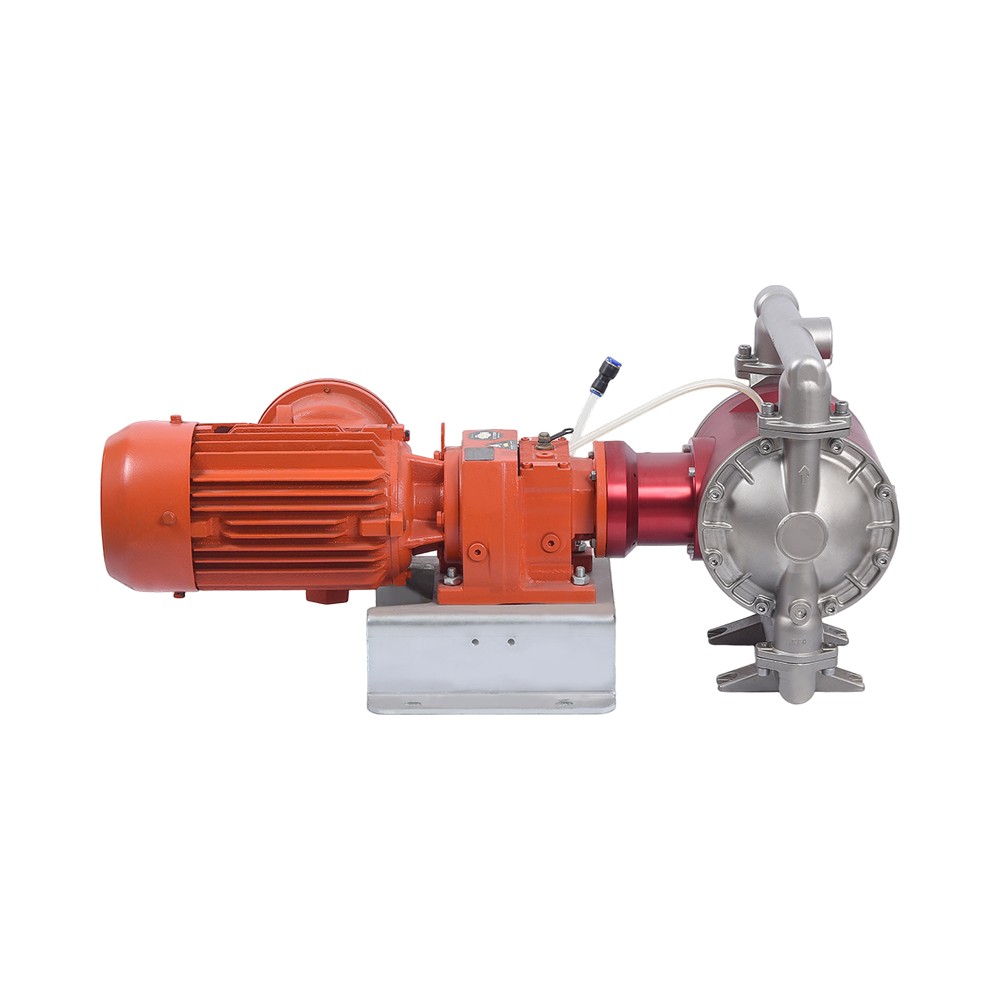
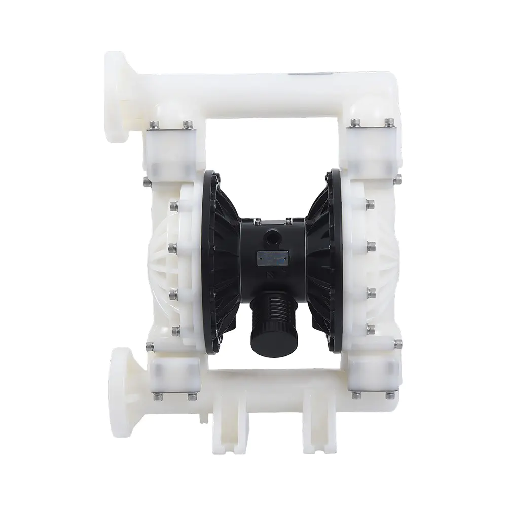
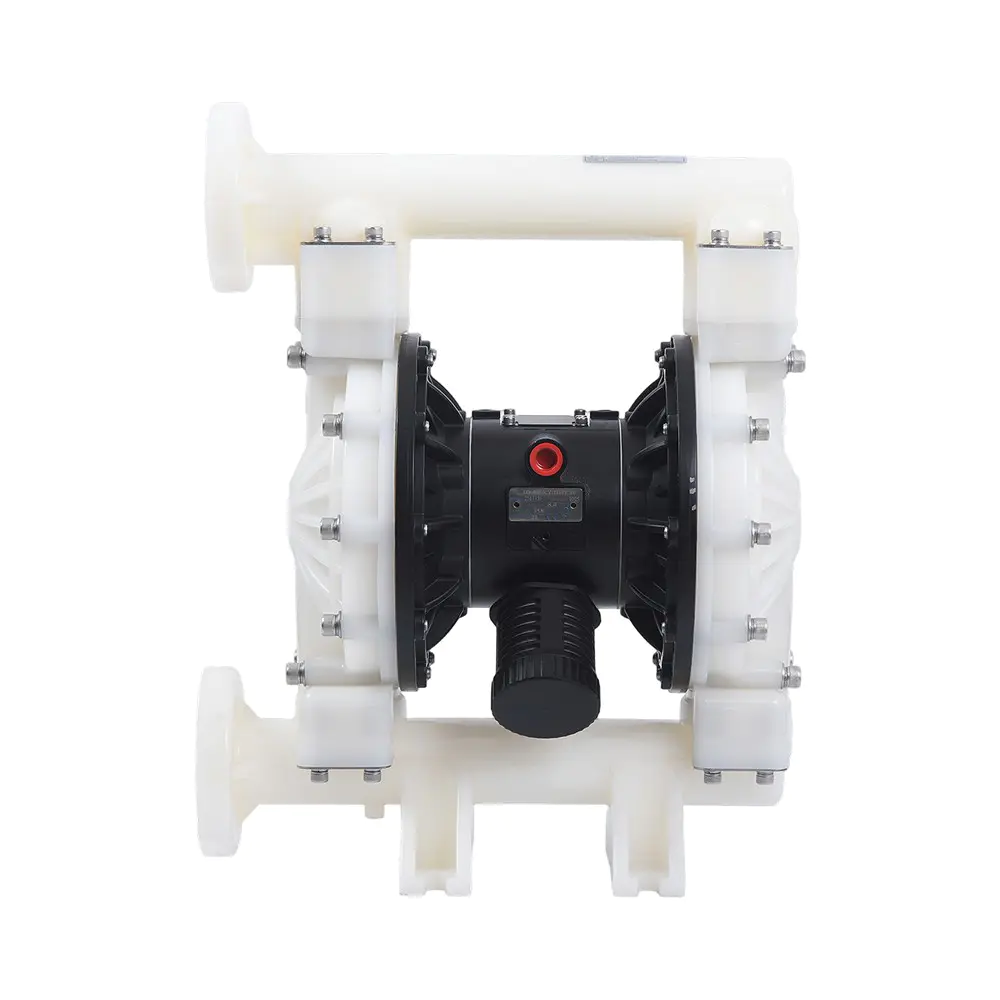
عربىA hydraulic diaphragm pump moves fluid by using hydraulic oil on one side of a flexible diaphragm to create suction and discharge strokes, completely isolating the pumped liquid from the drive end. This design eliminates dynamic seals and makes it possible to handle abrasive slurries, corrosive chemicals, and high-viscosity substances with outstanding reliability. Unlike simple mechanical diaphragm pumps, the hydraulic version uses a piston-driven oil chamber that evenly distributes pressure across the entire diaphragm surface, dramatically extending diaphragm life and enabling pressures above 200 bar.
Content
- 1 What Is a Hydraulic Diaphragm Pump?
- 2 How the Working Cycle Operates
- 3 Core Components Explained
- 4 Hydraulic Diaphragm Pump vs. Mechanical Diaphragm Pump
- 5 Advantages and Limitations at a Glance
- 6 Where Hydraulic Diaphragm Pumps Are Used
- 7 Maintenance Practices That Extend Service Life
- 8 Frequently Asked Questions
What Is a Hydraulic Diaphragm Pump?
A hydraulic diaphragm pump is a positive displacement pump that uses a reciprocating piston to pressurize hydraulic oil, which in turn flexes a diaphragm to move the process fluid. The diaphragm serves as both a separation membrane and a pumping element, ensuring zero leakage and eliminating the need for gland packing or mechanical seals. According to the Hydraulic Institute, these pumps routinely achieve volumetric efficiencies between 88% and 95% when handling clean liquids, and they can maintain more than 85% efficiency even with fluids containing up to 60% solids by volume.
The most defining characteristic is the presence of an intermediate hydraulic chamber filled with oil. That oil transmits motion uniformly, which prevents stress concentrations that typically cause premature diaphragm failure in mechanically coupled designs. In 2024, industry maintenance data compiled by Pump Industry Insights showed that well-maintained hydraulic units had a mean time between diaphragm replacements exceeding 20,000 operating hours.
How the Working Cycle Operates
A hydraulic diaphragm pump executes a four-stage reciprocating cycle that converts rotary motion into a smooth, pulse-minimized fluid flow. The cycle relies on the incompressibility of hydraulic oil to faithfully replicate piston displacement on the diaphragm surface. The following ordered list breaks down each stroke precisely.
- Suction stroke – piston retraction. The piston moves backward inside the hydraulic cylinder. This reduces pressure in the oil chamber, pulling the diaphragm away from the pump head. The process fluid inlet check valve opens, and liquid enters the pump cavity. A typical 50 mm stroke can generate a suction lift capability of up to 5 meters for water-like fluids.
- Transition – diaphragm reversal. At the end of the suction stroke, both check valves are momentarily seated. The hydraulic oil pressure stabilizes, and the diaphragm reaches its fully retracted position. In advanced designs, a built-in refill valve compensates for any oil loss during this phase.
- Discharge stroke – piston advance. The piston moves forward, pressurizing the hydraulic oil. The diaphragm is pushed into the pump head, decreasing the volume of the fluid chamber. The outlet check valve opens, and the liquid is displaced. Discharge pressure can reach 350 bar in high-pressure models, based on Hydraulic Institute performance standards.
- Completion – pressure equalization. The piston completes its forward travel. The diaphragm presses against the pump head contour, leaving minimal clearance volume. The outlet valve closes, the inlet valve remains shut, and the cycle restarts. This minimal dead volume helps the pump achieve a suction lift recovery within a single crank revolution.
This sequence repeats at speeds typically between 60 and 180 strokes per minute. According to performance curves published by the Hydraulic Institute, the flow rate of a hydraulic diaphragm pump remains linear within 2% across its entire pressure range, provided the hydraulic oil is properly maintained and air is fully purged.
Schematic cross‑section of a hydraulic diaphragm pump illustrating the drive, piston, oil chamber, diaphragm, and check valves.
Core Components Explained
Every hydraulic diaphragm pump shares seven essential building blocks that collectively determine performance, safety, and service intervals. Understanding each one clarifies why these pumps tolerate operating conditions that destroy conventional centrifugal or gear pumps within hours.
Drive End and Piston Assembly
The drive end converts rotary motion from an electric motor or engine into linear piston movement through a crankshaft and connecting rod mechanism. A 2025 teardown analysis of high-cycling units showed that forged steel connecting rods with crosshead guidance reduce side loading by 40% compared with simple slider-crank layouts, cutting hydraulic oil contamination.
Hydraulic Oil Chamber and Refill System
The oil chamber sits between the piston and the diaphragm, transmitting force while lubricating moving parts. A dedicated refill valve automatically replenishes any oil that escapes past the piston seal. Without this subsystem, even a 2% loss of hydraulic oil would reduce discharge volume proportionally.
Diaphragm and Material Selection
The diaphragm is the central separating element that flexes under hydraulic pressure to create suction and discharge. Manufacturers offer PTFE, EPDM, Nitrile, and FKM diaphragms for different chemical compatibilities. A PTFE diaphragm operating at 25°C in a chlor-alkali service can exceed 18,000 hours of life, whereas EPDM in abrasive mining slurry may need replacement after 6,000 hours according to field studies by the Hydraulic Institute.
Check Valves and Flow Path
Inlet and outlet check valves control unidirectional flow. Ball-type valves handle particulates up to 8 mm without clogging, while flap valves reduce pressure loss in high-flow applications. The Hydraulic Institute reports that switching from spring-loaded ball valves to gravity-assisted flap valves can improve net positive suction head margin by 0.4 bar in viscous services.
Pressure Relief and Safety Systems
An internal pressure relief valve protects the diaphragm from over-pressurization on the hydraulic oil side. When discharge line blockage occurs, the relief valve opens at a preset limit, typically 10–15% above maximum working pressure, returning oil to the reservoir and preventing diaphragm rupture.
Hydraulic Diaphragm Pump vs. Mechanical Diaphragm Pump
The hydraulic version uses oil coupling while the mechanical version relies on a physical linkage connected directly to the diaphragm center. This fundamental difference leads to a wide performance gap. The table below contrasts the two technologies on parameters critical to industrial users.
| Parameter | Hydraulic Diaphragm Pump | Mechanical Diaphragm Pump |
|---|---|---|
| Maximum discharge pressure | 350 bar | 12 bar |
| Diaphragm stress distribution | Uniform oil pressure | Point load at center bolt |
| Typical diaphragm life | 8,000 – 25,000 hours | 1,500 – 5,000 hours |
| Dry-run tolerance | Unlimited (oil lubricates) | Limited to minutes |
| Flow per pump head | Up to 200 m³/h | Up to 45 m³/h |
| Solids handling | Up to 60% by volume | Typically below 20% |
Advantages and Limitations at a Glance
A hydraulic diaphragm pump stands out for its ability to combine high pressure with sealless integrity, but it also demands careful hydraulic oil management. The grid below organizes the most decisive pros and cons based on operator feedback collected in a 2025 industrial pump survey involving 340 process plants.
Sealless Zero-Leak Design
No mechanical seal or packing means zero fugitive emissions. The EPA’s 2023 leak-reduction study noted that converting from packed plunger pumps to hydraulic diaphragm pumps cut volatile organic compound leaks by 98%.
Exceptional Solids Tolerance
With correct valve selection, the pump transfers slurries up to 60% solids. In mine dewatering trials, 20 mm diameter stone passed without jamming the ball valves, according to a 2024 mining technology report.
Oil Management Required
Hydraulic oil must be monitored for contamination and level. A drop in oil viscosity below 15 cSt can reduce volumetric efficiency by up to 12%, based on lab tests published by Pump Technology International.
Higher Initial Cost
A hydraulic unit typically costs 2.5 to 3 times more than a mechanically actuated diaphragm pump of equal flow. However, the Hydraulic Institute life-cycle cost calculator shows payback within 14 months when diaphragm replacement savings are factored in.
Where Hydraulic Diaphragm Pumps Are Used
Because a hydraulic diaphragm pump handles aggressive fluids while maintaining a hermetically sealed environment, it appears in sectors where failure is not an option. The following list highlights the five largest application segments based on global shipment data from Grand View Research (2025).
- Chemical processing – concentrated acids, alkalis, and solvents at temperatures up to 120°C. Over 28% of all hydraulic diaphragm pumps sold in 2024 served the chemical industry.
- Mining and mineral processing – abrasive tailings, thickener underflow, and reagent dosing. In Chilean copper mines, these pumps maintain 92% availability in 24/7 slurry circuits.
- Oil and gas – produced water reinjection, methanol injection, and drilling mud transfer. The sealless construction satisfies API 675 requirements for hazardous-area operation.
- Food and beverage – yeast slurries, chocolate mass, and CIP chemicals. Sanitary diaphragm options meet 3-A and EHEDG standards.
- Water treatment – sludge transfer, lime slurry, and polymer dosing. A single large hydraulic diaphragm unit can replace up to four progressive cavity pumps in a municipal plant, reducing footprint by 60%.
Maintenance Practices That Extend Service Life
Scheduled maintenance on a hydraulic diaphragm pump revolves around three pillars: hydraulic oil integrity, diaphragm condition monitoring, and check valve cleaning. Applying the protocols below can extend mean time between overhauls beyond 25,000 hours.
- Oil analysis every 500 hours. Check viscosity, water content, and particle count. Replace oil if ISO 4406 cleanliness code exceeds 18/16/13.
- Diaphragm leakage detection. Use a double-diaphragm setup with a pressure sensor in the intermediate chamber. A 2024 case study at a German chemical plant showed that early leak detection reduced unscheduled downtime by 74%.
- Check valve inspection quarterly. Remove and clean ball seats, especially when pumping crystallizing fluids. Replacing ball guides before they wear prevents seat damage.
- Relief valve calibration annually. Verify set pressure on a test bench. An out-of-spec relief valve can expose the diaphragm to overpressure and fail within days.
- Piston seal replacement at 8,000 hours. Even minor oil bypass reduces flow consistency. Replacing seals proactively costs 60% less than a full oil contamination clean-up.
Frequently Asked Questions
Can a hydraulic diaphragm pump run dry indefinitely?
Yes. The hydraulic oil lubricates the piston and cools the diaphragm from the back side. Extensive dry-run tests conducted by the Hydraulic Institute in 2024 confirmed that continuous dry operation for 72 hours caused no measurable damage, provided the oil reservoir was at the correct level and temperature stayed below 70°C.
How does temperature affect pump performance?
Hydraulic oil viscosity drops as temperature rises, which can reduce volumetric efficiency. Data from a Gulf Coast refinery showed that at 80°C oil temperature, flow rate decreased by 4.5% compared with the 40°C baseline. Installing an oil cooler or using synthetic high-temperature hydraulic fluid keeps the loss below 2%.
What is the typical payback period compared with mechanical diaphragm pumps?
Although the initial purchase price is higher, the Hydraulic Institute’s life-cycle cost analysis indicates a median payback of 14 months for a 15 kW unit operating 6,000 hours per year. The savings come primarily from fewer diaphragm replacements and reduced process downtime.
Does the pump require pulsation dampening?
A simplex hydraulic diaphragm pump generates a pulsating flow inherent to reciprocating action. Adding a pulsation dampener reduces pressure variation to less than 3% of setpoint. In metering applications, triplex pump heads with phased pistons bring residual pulsation below 1.5% without an external dampener.
The hydraulic diaphragm pump continues to gain market share in severe-service fluid handling because it solves the classic trade-off between high pressure and contamination-free operation. With ongoing improvements in diaphragm materials and oil-refill automation, the technology is expected to capture an additional 12% of the positive displacement pump market by 2028, according to the 2025 industry outlook from Frost & Sullivan. For plant operators and engineers, understanding the working principle in detail is the first step toward specifying a pump that will deliver reliable performance for decades.